
It is inflatable, can suck slurry, has large slurry circulation volume, low power consumption and strong production capacity.
【Processing Capacity】:0.5~38m3/min
【Effective volume】:2~40m3
【Application Environment】: CLF flotation machine is mostly used to separate non-ferrous and ferrous metals and chemical raw materials. It is suitable for coarse-grained separation. At the same time, it can also take into account fine-grained separation.

15311826613
Click to add WeChatXinhai CLF type coarse particle flotation machine has two forms: straight flow tank and slurry suction tank. The main difference lies in the impeller structure. The straight flow tank uses a single blade impeller. It cooperates with the tank body to produce a large circulation of slurry in the tank and disperse it. The air effect is good. Generally, the particle size range of conventional flotation machines is 0.01-0.15mm, and the processing range of CLF coarse particle flotation machines is 0.4-0.7mm.
The impeller and stator system of the CLF coarse particle flotation machine adopts a new design. It uses a new slurry circulation method to effectively improve the load capacity of mineralized bubbles. In addition, it can also increase the amount of floated minerals. The particle size of the slurry returned to the impeller area is low, the particle size is fine, and the power consumption is low;
The independent blower has a large aeration volume and good air dispersion, which is easy to form large bubbles and improve The probability of mineral particles adhering to bubbles improves the ability of bubbles to carry mineral particles;
The coarse mineral particles stay in the slurry for a short period of time, and the mineralized foam has a short lifting distance, which reduces the probability of mineral particles falling off and improves the floating distance of coarse mineral particles. Choose ability.
The structure of clf type coarse particle flotation machine mainly consists of air distributor, stator, rotor, tank, bearing, motor, hollow spindle, grid plate, circulation channel, partition, false bottom, It consists of mid-mine return pipe, central cylinder, nozzle and cover plate.
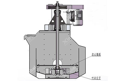
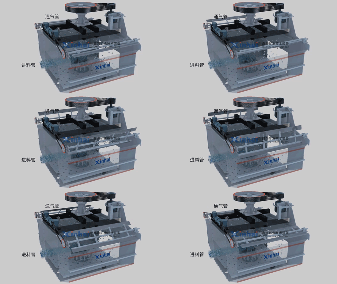
The working principle of the Clf flotation machine is that when the impeller of the flotation machine rotates, the low-pressure air supplied by the blower enters the air distributor in the center of the impeller through the hollow shaft, and enters between the impeller blades through the holes around the distributor. At the same time, under the false bottom The slurry is sucked into the space between the impeller blades from the bottom of the impeller. After the slurry and air are fully mixed between the impeller blades, it is discharged from the periphery of the impeller. The discharged slurry-air mixture enters the inner area of the tank after a steady flow through the stator.
At this time, the slurry in the internal area of the flotation machine will contain a large number of bubbles. The slurry in the external circulation area does not contain bubbles under ideal conditions, causing a pressure difference between the internal and external slurries. Between the pressure difference and the impeller Under the action of suction, the internal slurry and bubbles rise together at the required flow rate and pass through the grid plate, bringing the coarse-grained minerals to the grid plate to form a coarse-grained mineral suspension layer, while the bubbles and minerals containing more fine particles Continuing to rise, a foam layer is formed when it rises to the liquid level, and the slurry containing more fine-grained minerals crosses the grate and enters the impeller area through the circulation channel to participate in recirculation.
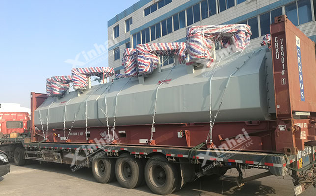
CLF flotation machine equipment is ready for use
On-site installation and commissioning of CLF coarse particle flotation machine
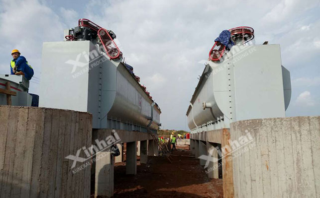
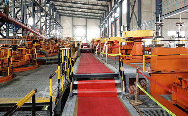
CLF coarse particle flotation machine at a mineral processing plant site
| Model | CLF-2 | CLF-4 | CLF-8 | CLF-16 | CLF-30 | CLF-40 | |||
| Effective volume | 2 | 4 | 6 | 16 | 30 | 40 | |||
| Tank size (length × width × height) mm | 1200×1600×1250 | 1600×2100×1500 | 1900×2500×1950 | 2500×3200×2400 | 3300×4000×3000 | φ4200×3900 | |||
| Production capacity m3/min | 0.5-2 | 1-4 | 1-6 | 4-16 | 7-30 | 8-38 | |||
| Inspiratory volumem3/(m2.min) | 1.5 | 1.5 | 1.5 | 1.5 | 1.5 | 1.5 | |||
| Spindle motor | Model | suction tank | Y160M-6 | Y200L-8 | Y200L2-6 | Y280S-6 | Y315M-8 | Y315M-8 | |
| DC tank | Y132M2-6 | Y180L-8 | Y200L-8 | Y280S-8 | Y315S-8 | ||||
| Power kw | suction tank | 7.5 | 15 | 22 | 45 | 75 | 75 | ||
| DC tank | 5.5 | 11 | 15 | 37 | 55 | ||||
| 转速r/min | suction tank | 790 | 730 | 790 | 730 | 740 | 740 | ||
| DC tank | 790 | 730 | 730 | 730 | 740 | ||||
| 叶轮 | Diameter mm | suction tank | 460 | 620 | 750 | 790 | 1110 | 1090 | |
| DC tank | 410 | 580 | 645 | 750 | 880 | ||||
| Scraper motor | Model | Y100L-6 | Y100L-6 | Y100L-6 | Y100L-6 | Y100L-6 | Y100L-6 | ||
| Power kw | 1.5 | 1.5 | 1.5 | 1.5 | 1.5 | 1.5 | |||
| Scraper speedr/min | 16 | 16 | 16 | 16 | 16 | 16 | |||
| Equipment weight (single slot)kg | suction tank | 1591 | 3002 | 5168 | 9230 | 17010 | 23690 | ||
| DC tank | 1481 | 2702 | 4654 | 8970 | 15950 | ||||